|
Creating a Simple Figure From Existing Props
|
 |
|
by: Thorne
|
|
|
Tools required:
Poser, a good text editor... I recommend EditPad Lite which is a free version of EditPad Pro, and is available here:
http://www.editpadpro.com/editpadlite.html
(Using WordPad is not recommended).
This is a walk-through tutorial by which we will create a simple, posable faerie wings figure from two existing props- right and left wing. First you will also need the wing props. Get them here:
http://www.faeriewylde.com/tutorials/TutWings.zip
The wings are named WingL and WingR. The R(ight) and L(eft) are referenced to the FIGURE'S right and left, NOT the user's (that would be YOU). The parameters used in this tutorial have been calculated using the DAZ Millennium Girl PT figure. Other, larger (or smaller) figures will require adjusting scale and position to your liking.
(screenshots used in this tutorial are taken from Poser v.4)
|
|
Steps:
1. Import the Props
The wing props are separate OBJ format objects which will first need to be combined into a single object in order to create a single-body, posable figure. We will start from scratch and assume that we have no idea of what the scale of the props is going to be in relation to the Poser figures that will be used with them. Poser uses the "figure size" scale which has no meaning to the rest of the world, other than the fact Poser scale is very small compared to most modeling applications. If you import the OBJ wing props with no scale setting, they are likely to be very huge compared to the figure that will wear them, and it is more desirable to have them at just the right size when the wings are scaled to 100%. A good faerie wings-to-faerie ratio is about 50%, and that can be adjusted slightly once the props are imported. Also since we have no idea where the objects might appear in the Poser scene once they are loaded, we will control the position as well with our import dialog box settings.
|
Import the two wing object files, WingL.obj and WingR.obj, one at a time into your default Poser setup using the Poser menu function:
File:Import:Wavefront OBJ (see figure 1.)
|

figure 1. |

figure 2. |
When the import dialog box appears, use ONLY the following settings settings (figure 2). Leave all other options unchecked.
Centered
Place on floor
Percent of standard figure size: 50
You should now have two wings standing in the center of the floor superimposed on top each other. Next they need to be positioned.
(Important Note: Import the LEFT wing WingL.obj into Poser first, then import the RIGHT wing WingR.obj last. The reason for this is explained in step 5.)
|
|
2. Position the Props
After both wings have been loaded in this way, position them using the following translation coordinates. For WingL use:
xTrans = +0.140
yTrans = +0.285
ZTrans = -0.450
For WingR use:
xTrans = -0.140
yTrans = +0.285
ZTrans = -0.450
As stated above, these settings are optimized for using the wings with the DAZ Millenium Girl PT figure (see figure 3). To use them with Victoria, Stephanie, or some other figure, NOW is the time to load one of those figures into your Poser scene and adjust the wings positions to more adequately fit the figure being used. For this tutorial, be sure that the right and left wings have identical yTrans and zTrans settings. The xTrans coordinate will be the same number, MINUS (-) for the WingR (figure's right wing) and PLUS (+) for the WingL.
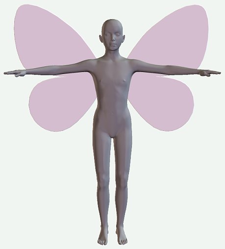
figure 3. |
|
3. Export the Object
Generally you would create your figure geometry originally to contain all the separate groups, named accordingly, that make up the figure. The purpose of this tutorial however is to transform already existing prop objects into a posable figure. With that in mind, now we need to create a single object geometry from the two props we just imported. To do this, use the Poser menu function:
File:Export:Wavefront OBJ
This function will bring you a series of dialog boxes with options. The first dialog box to appear is simply the Export Range, in number of frames, and it is default set to 1 (see figure 4). Click "OK" and move on to the next dialog box.
|

figure 4. |
The second dialog box is where you select which objects to export. Select BOTH the WingR and WingL objects that you have just recently imported. Be sure that nothing else is checked.(see figure 5)
|

figure 5. |
Finally, Poser will ask you for specific OBJ format export options. Be SURE to check ONLY the option:
Include existing groups in polygon groups (see figure 6)
|
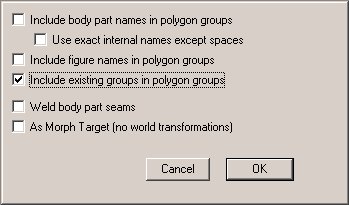
figure 6. |
When the file browser box appears, save the OBJ file into your Poser root directory, using this EXACT name and path:
Runtime\Geometries\ThorneWorks\TutWings.obj
|
|
4. Create the Hierarchy File
(This step has actually already been done for you, in that the PHI file has been included. However you should read it anyway to know what's going on, and in case you ever want to build one for yourself.)
The following is what is contained within the included PHI (Poser hierarchy) file named "TutWings.phi":
|
objFile :Runtime:Geometries:ThorneWorks:TutWings.obj
1 WingR yzx
1 WingL yzx
|
|
Now, using EditPad Lite or your text editor, open this PHI file. The PHI format is a Poser Hierarchy file, which tells the application how a figure to be created should be hinged together. It is very important to note the names of the body parts as they are listed in the PHI file. There are other, better descriptions of Poser PHI files available, but here's a quick rundown of what the lines mean:
objFile :Runtime:Geometries:ThorneWorks:TutWings.obj
This line tells the location and name of the Poser geometry file that will make up this figure. Notice this is the same name and location as we saved the combined prop object file in Step 3 above. Use the Poser convention of colons in the folder path, and don't forget the space after the Poser keyword, "objFile".
The next section is the part names and herarchy. Each part is listed on a separate line.
1 WingL yzx
The first number is the position in the figure parts parenting hierarchy. Since we want the two wings to move independantly of each other, both wings will be assigned a "1" as the top hierarchy. In just a moment when Poser creates the figure, there is a "body" figure part automatically assigned which will have its own translation, scale, and and rotational parameter dials when selected in Poser. The "Body" part is automatically created internally by Poser and it does not need to appear in the PHI hierarchy file. This why it is also not necessary to create a third small or invisible part as a wing "pivot", the automatically assigned "Body" part works well for this.
Next in the line comes the body part name. VERY IMPORTANT! The part names listed here in the hierarchy file MUST be identical to the internal group names of the OBJ single wings object we just exported in Step 3. Don't let this worry you now however, we are going to make sure that everything matches in Step 5, with a little bit of internal geometry magic ;o)
The final part of the line, "yzx" is what is called the rotational "order" of the named body part. The first position is the "spin" axis, in this case the Y axis. In the next coordinate position is Z, meaning that the wings are likely to become 90 degrees on the Poser Z axis before they would on the Poser X axis. If you're not quite sure what all that means, just remember that most of the time for wings, this is the rotational order that will be used: yzx
Note: This same PHI file can be used for any two-part wing figure. Just be sure to change the name of the OBJ file/path in the first line to point to your new geometry. And, you might want to change the file name ;o)
|
|
5. Verify Geometry Groups
This is going to be the most complicated step, but truthfully it sounds more complicated than it really is- once you've done a couple of these it will seem easy. Poser uses the OBJ file format for its geometry files, and this is simply a text file with certain key letters used to begin each line in the file, in order to identify what the function of the line is.
As stated earlier, most of the time you would already have your group names set at the time your geometry is created. However, in the case that you are using a third party geometry, you want to be certain that the internal group names in your OBJ geometry file exactly match the group names you have given in your PHI hierarchy file (as shown above). Here's how...
One of the key letters used in the OBJ file format is "g", which means that ALL lines within the OBJ text file that begin with the letter "g" are GROUP NAMES. So, first open the file "TutWings.obj" using EditPad Lite or your own other text editor. When we saved the two wing props combined as a single object, Poser simply concatenated the two props together and exported them as a single text file.
Take note at the very top of the file there will be a few lines beginning with the # symbol, among them:
# InternalName: WingL
# ExternalName: WingL
The # symbol at the beginning of a line means these lines are comments and are not read as part of the geometry. However, some of these lines at the top of the file will say either "WingL" or "WingR" (depending on which one you imported into Poser first way back in step 1). At this point you only need to remember which wing it is, because that means it's the first one in the file. If you followed the directions in step 1, this should be the LEFT wing, WingL. ;o)
So now we want to search this OBJ text file for the group names, to be sure they match the PHI file. We are searching specifically for lines that begin with the lowercase letter "g". The first of these you will find will be at or around line number 1130. The surrounding lines will look like this:
mtllib TutWings.mtl
g
g Free_Form
usemtl wing
What does it all mean?? Well... first of all, you should DELETE the line that says "mtllib". That's right, just go ahead and delete it because it is NEVER used. See that second line under that which has nothing but the letter "g" on it? DELETE that line as well. We do not need it. Now the next line that says "g Free_Form" is the line we want to change. Remember the wing name in the comment line at the top of the file? This is the name you want to use here.
REPLACE the text "Free_Form" with the text "WingL". Congratulations! You've just renamed an internal OBJ group! The next line under that that says "usemtl wing" is where the material region for this wing is named. You may change this material name as well if you wish, something such as "left_wing" perhaps. Be sure to leave the OBJ keyword, "usemtl" on the line, and only change the region name, "wing".
Next, continue searching for those "g" lines until you come to the second group. The next "g" line you are interested in will be at or around line number 2672. Again, you will see lines similar to those on the first group:
g
g Free_Form
usemtl wing
This time, delete the line that only has the single letter "g", then on the next line replace the text "Free_Form" with the text "WingR". You may also change the material region name "wing" to "right_wing" if you wish.
And THAT will be about enough of THAT! Do you see now what we have done? We have edited an OBJ geometry file in order to have the internal group names to be EXACTLY what we want them to be. Also perhaps we got a little creative with material region names. But now that's all done!
( Note: If you leave the two material regions with the same name, "wing", they will not be read as two regions, so you will only have one material region that will show up in your Poser materials window. That's okay, the texture template will still work.)
|
|
6. Convert the Hierarchy File
We are ready to create a figure. Use the Poser menu function:
File:Convert Hier File (see figure 7)
|
When the file browser box appears, select the PHI that was included in the ZIP, "WingTut.phi" from wherever you have placed it. Poser will then automatically create a new figure using the geometry and hierarchy specified within the PHI file. Finally, Poser will ask you to name the new creation. For the purposes of this tutorial, name the new figure "TutWings". The new figure will be automatically stored in your New Figures character library folder, with the name you have given it. Don't worry about the thumbnail image just yet, we are not finished... ;o)
|
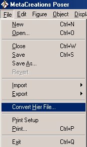
figure 7. |
|
7. Adjust Joint Parameters
Almost done! Just a bit more... The last adjustment needed in the creation of our new wings figure is to set the joint parameters for proper rotation of the wings. This is done in the Joint Editor window, found under the Poser Window menu (figure 8).
|
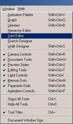
figure 8. |
To set joint params, it is easier to see what you're doing if you change the document display mode to outline, as seen in figure 9. Select the right wing first (figure's right or stage right). In the Joint Editor window the three parameters labeled "Center Point:" are the X, Y, and Z coordinates for the center of rotation, respectively. Set these coordinates for right wing body part, WingR, as follows:
X = -0.015
Y = +0.437
Z = -0.045
After that is done, select the left wing part and set the center point with the same coordinates, except change the sign of the X coordinate to X = +0.015 (plus X).
|
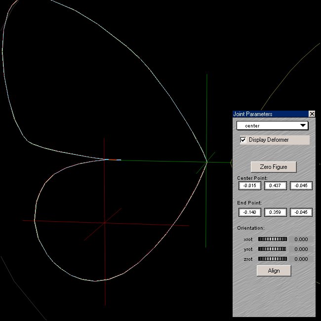
figure 9. |
Where did those funny numbers come from? Well, see those little green crosshairs in figure 9? I moved them around by changing the numbers in the joint Editor window until the crosshairs were exactly where I wanted the center of rotation to be. Tada! ;o)
|
|
8. PLAY!
Now the wings are ready to fly! The last thing to do is apply a texture map. You can use the cheesy blue one provided in the ZIP file, or create one of your own using the texture template (also included). After applying a texture, save your new wing figure in the figure library folder of your choice, and delete the original one in New Figures.
|

|
To apply the wings to another figure, use the positioning dials on the wings body part, selected from the scene element menu. Then use the Figure menu and set the figure parent to be the other figure's chest part. This is all that is needed for the wings to follow your faerie anywhere!
|
|
Parts of this procedure may seem to be a bit difficult, but with a little practice you should be able to convert a couple of prop objects into a posable wings figure, including setting the joint parameters, in less than 30 minutes. The real secret is in editing the OBJ text file, to ensure that Poser will recognize all the proper body parts within the PHI hierarchy file which it (Poser) uses to create the figure.
Happy Winging!
|
|
Back To:


|
|
All page contents COPYRIGHT © 2003 by ThorneWorks
ALL RIGHTS RESERVED
|